


|
Navigation: Library > Iconic Diagrams > Hydraulics > Valves > Basic Valves > LoopFlushingValve |
  
|
Iconic Diagrams\Hydraulics\Valves\Basic Valves
Domains: Continuous. Size: 1-D. Kind: Iconic Diagrams (Hydraulics).
Loop flushing valves are used to maintain a high quality working fluid in closed hydraulic circuits. In closed hydraulic circuits the oil is continuously flowing from a pump to an actuator. A loop flushing valve allows the oil to leave the circuit for cooling and filtering. If one side (pa) of the valve has a higher pressure, oil will flow from the other side (pb) out of the closed circuit and vice versa.
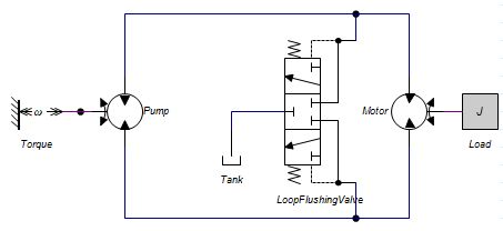
The circuit is always equipped (not shown above) with a charge pump to keep the suction side of the pump on a pre-pressure to avoid cavitation and so damage to the pump, and to exchange the fluid that is flushed.
Loop flushing valves are spring operated. I.e. a certain pressure difference between port a and b is required to open the valve. This pressure can be adjusted and is indicated by the parameter p_sw.
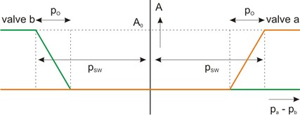
A small pressure difference is required to turn a valve from completely closed to completely opened. This overlap pressure is indicated by the parameter p_o.
Ports |
Description |
pa, pb p_out |
Input terminals of the valve. Output terminal. |
Causality |
|
fixed volume flow out pa fixed volume flow out pb fixed volume flow out p_out |
|
Parameters |
|
p_o p_sw Q_nom p_nom f d GLeak |
Overlap pressure [Pa]. Switching pressure [Pa]. Turbulent flow at nominal pressure drop [m3/s] Nominal pressure [Pa]. Bandwidth of the spool dynamics [Hz], f > 0, (hidden). Damping of the spool dynamics [], d > 0, (hidden). Conductance of the laminar leakage flows [m3/s.Pa], GLeak >= 0. (hidden). |