Anti-Windup |
  
|
All actuators have physical limitations, a control valve cannot be more than fully open or fully closed, a motor has limited velocity, etc. This has severe consequences for control. Integral action in a PID controller is an unstable mode. This does not cause any difficulties when the loop is closed. The feedback loop will, however, be broken when the actuator saturates because the output of the saturating element is then not influenced by its input. The unstable mode in the controller may then drift to very large values. When the actuator desaturates it may then take a long time for the system to recover. It may also happen that the actuator bounces several time between high and low values before the system recovers.
Integrator windup is illustrated in the figure below, which shows simulation of a system where the process dynamics is a saturation at a level of ±0.1 followed by a linear system with the transfer function:
![]()
|
|
Because of the saturation in the actuator, the control signal saturates immediately when the step is applied. The control signal then remains in saturation level and the feedback is broken. The integral part continues to increase because the error (SP - PV) is positive. The integral part starts to decrease when the process output (PV) has become larger than the setpoint (SP), but the process output remains saturated because of the large integral part. Slowly the process output decreases towards the setpoint.
The net effect is that there is a large overshoot. This phenomenon is called "integrator windup". A good insight in windup is found when looking at the proportional band.
The values of the process output that correspond to the minimum and maximum output are denoted as ymax and ymin. The controller operates linearly only if the process output is in the range (ymax , ymin). The controller output saturates when the process output is outside this band. A good insight into the windup problem is obtained by investigating the range (ymax , ymin). All 20-sim controller models in parallel form with anti-windup scheme, have the extra variables PB_high and PB_low which are equal to ymax and ymin.
An illustration of the proportional band is given below. The same linear system is used with the same controller. As can be seen, the actuator is saturated from t = 0 until t = 14. At t = 14 the process output enters the range (PB_high , PB_low) and controller feedback is regained.
|
|
Integrator windup can be avoided, by making sure that the integral is kept to a proper value when the actuator saturates, so that the controller is ready to resume action, as soon as the control error changes. This anti-windup scheme is known as tracking or back calculation.
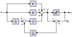
As well known form of tracking is linear feedback anti windup. It is shown in the figure below (parallel form). The actuator is represented by a signal limiter. The difference between actuator input and output (TR) is fed back to the integrator through the gain 1/Ta. As soon as the limiter saturates, this signal becomes non-zero and prevents the integrator from winding up. The tracking time constant Ta can be used to tune then amount of anti windup.
The same scheme can also be used for controllers with a series form. A diagram is shown below.
To prevent the integrator from saturating, the tracking time constant must be chosen small. Too small values, however decrease the controller performance. As a rule of thumb Åström suggested to choose the tracking time constant Td <= Ta <= Ti. Some authors prefer a good controller performance and suggest to choose Ta = Ti.
As long as the actuator output is equal to the controller output, anti-windup scheme will not be activated and the controller is in normal operation (control mode). When the actuator saturates, the anti-windup scheme will be activated and prevent the controller output from wandering away. In effect the anti-windup scheme matches the controller output and actuator output. This is why the actuator output is also known as the tracking signal (TR).
When an external actuator signal is used (external tracking signal) is is important to compensate for the actuator gain. Otherwise the tracking signal is not equal to the controller output, during normal operation and the anti-windup scheme is activated.
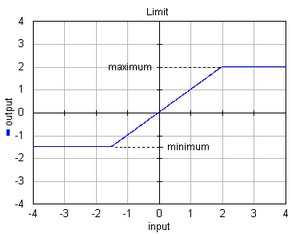
Anti-windup schemes are based on the difference between actuator input (controller output) and actuator output. These signals are not always available. Therefore an actuator model can be used inside the controller to yield this difference. In the library models, a signal limiter is used the actuator model:
output = minimum; (input < minimum)
output = input; (minimum <= input <= maximum)
output = maximum (input > maximum)