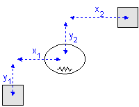
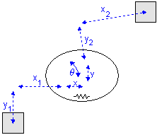
A TwoDSpring model represents a flexible spring between two bodies. The center of stiffness is located relative to the two bodies. The offsets from the bodies to the center of stiffness are indicated by x1, y1, x2 and y2 as shown in the picture below (left).


A 2-D spring in rest (left) and stretched (right).
Note that x1, y1, x2 and y2 are defined with respect to the spring coordinate frame which is at the center of the spring. This means in the picture above x1 and y1 have a negative value and x2 and y2 have a positive value.
When the spring is stretched the offsets will change by the spring elongations x, y and q as indicated in the picture (right). The center of stiffness is always located precisely in the middle of the spring elongations. Because all spring equations will be calculated from the center of stiffness this means that the offsets for a stretched spring are (x1 - x/2), (y1 - y/2), (x2 + x/2) and (y2 + y/2).
For a realistic representation of vibration behavior, every 2D spring has a damper in parallel. If you want to turn off the effects of this damper, choose the damping parameters equal to zero. If you want to damp out unwanted vibrations, choose the damping parameters equal to 0.1% to 10% of the spring parameters.
Take a look at the TwoDSpring model in the picture below. If we replace the spring in x-direction by a zero force we have created a linear slide.

Linear slide: x = free, y = stiff, q = stiff.
Consider a carriage that is clamped with four wheels to a slide. In the x-direction the carriage is free to move, which is equal to a zero force. The limited stiffness of the wheels is represented by springs. If there is a force with equal sign on both wheels, the carriage will slightly move in the y-direction. If there is a force with opposite sign on both wheels, the carriage will only rotate. This can be represented by two independent springs: one in the y-direction and q-direction.
If we repeat the same experiment and replace the spring in x-direction by a zero force and the spring in q-direction by a zero torque, we have created a linear slide with rotational freedom. In practice this can be found with carriages that are clamped with a limited set of wheels as shown below.

Linear slide: x = free, y = stiff, q = free.
The TwoDLibrary contains four Linear Slide models:
1 |
TwoDLinearSlide-X |
x = free, y = stiff, q = stiff |
2 |
TwoDLinearSlide-Y |
x = stiff, y = free, q = stiff |
3 |
TwoDLinearSlide-XTheta |
x = free, y = stiff, q = free |
4 |
TwoDLinearSlide-YTheta |
x = free, y = stiff, q = free |
Instead of replacing the spring in x-direction with a zero force as with the linear slides, we can replace it by a 1D power port to allow all kind of connections with the models from the standard library. In this way we have created a linear actuator, that allows every kind of actuation.

Like the linear slides, for the linear actuators we can also replace the spring in q-direction by a zero torque, which makes the total number of linear actuator models equal to four:
1 |
TwoDLinearActuator-X |
Fx and vx connected to a port |
2 |
TwoDLinearActuator-Y |
Fy and vy connected to a port |
3 |
TwoDLinearActuator-XTheta |
Fx and vx connected to a port, T = 0, w = 0 |
4 |
TwoDLinearActuator-YTheta |
Fy and vy connected to a port, T = 0, w = 0 |
With the port connection ever possible form of actuation can be created. Two examples are shown below.
